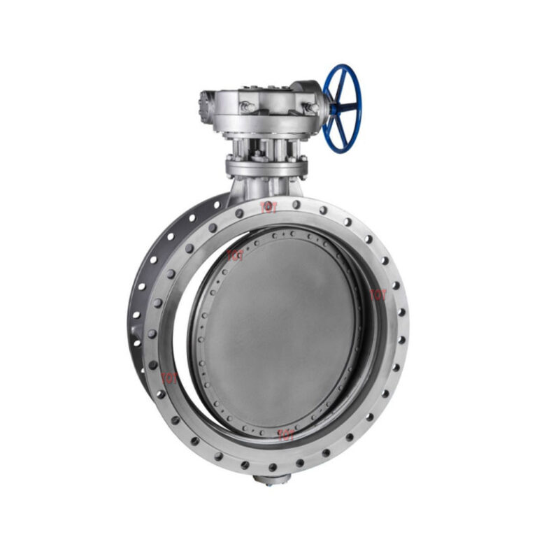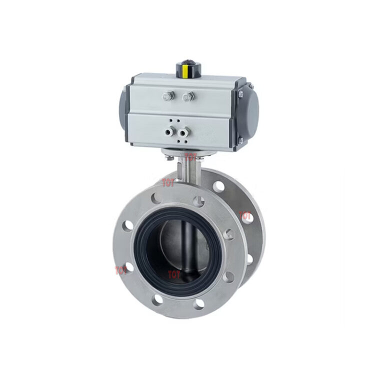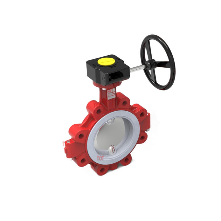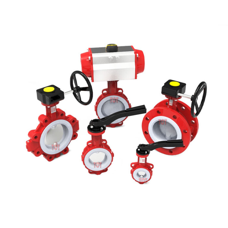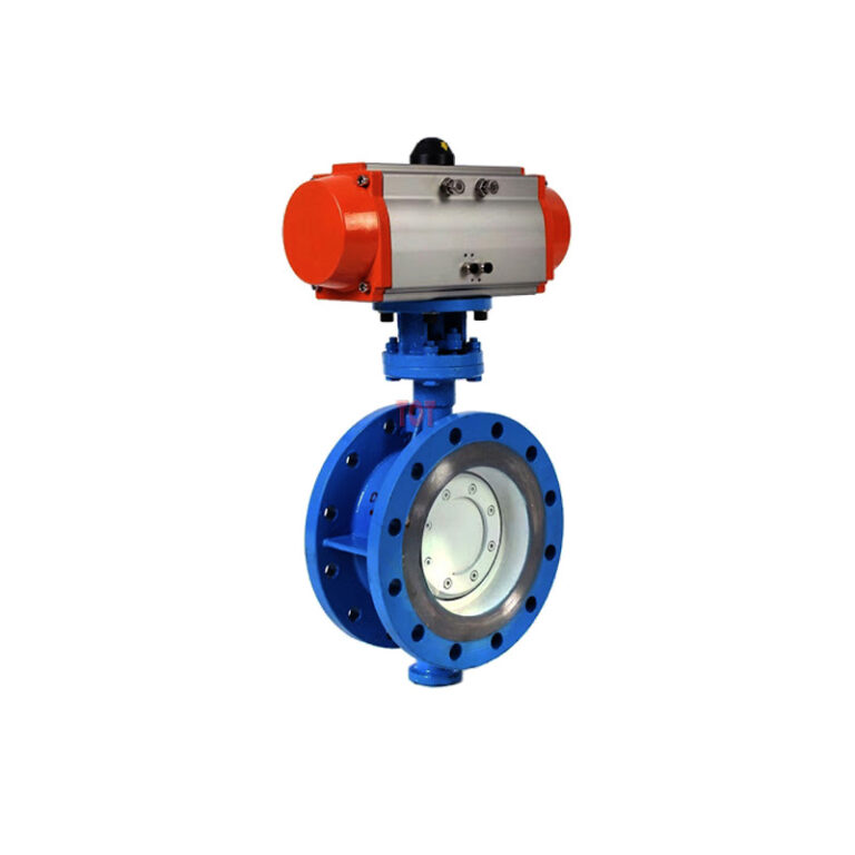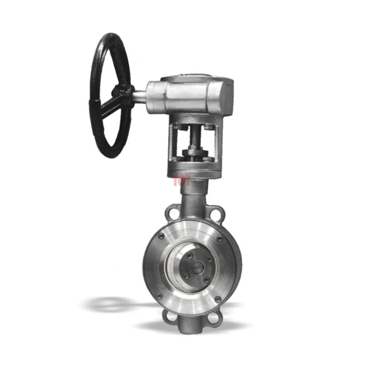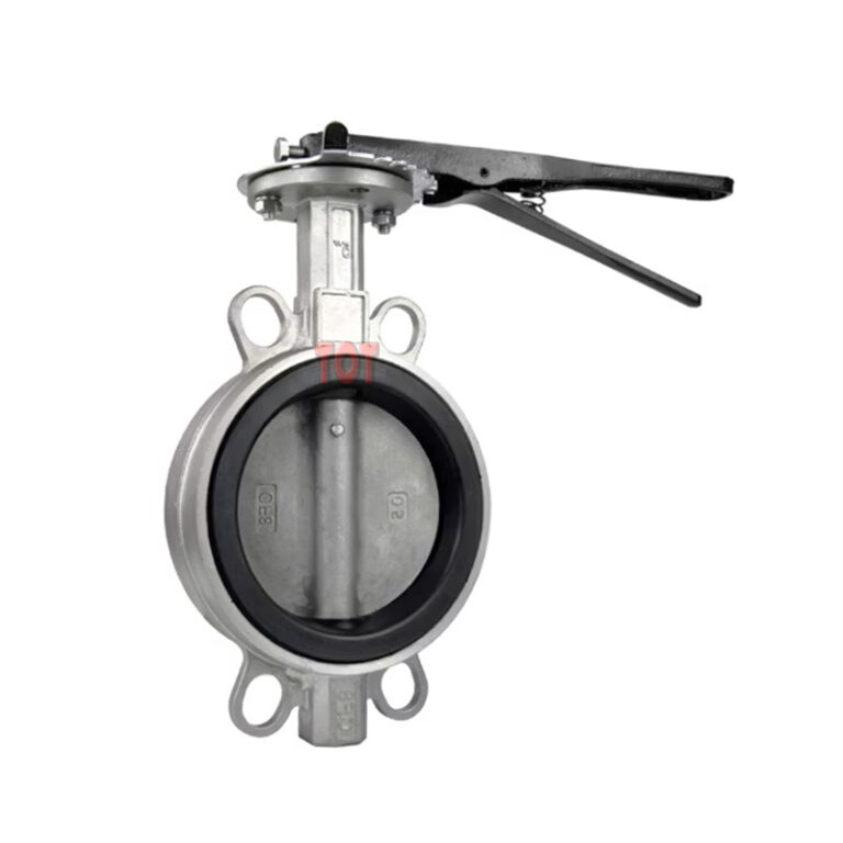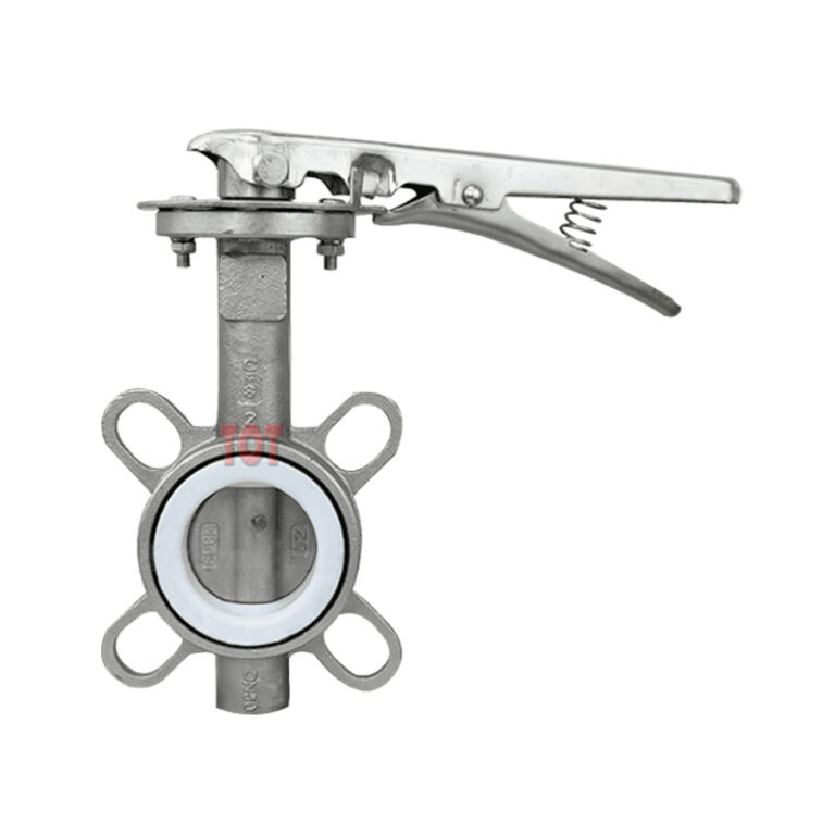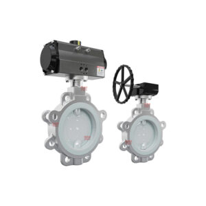
FEP Lined Butterfly Valve
FEP lined butterfly valves are butterfly valves that have a layer of FEP (Fluorinated ethylene propylene) material covering the media-contacting parts of the butterfly valve disc and valve body to improve its corrosion resistance and sealing performance.
Our FEP lined butterfly valves provide you with a reliable solution for controlling media flow in environments with corrosive chemicals, high temperatures or abrasives.
We offer FEP lined butterfly valves in a variety of sizes, pressure ratings and configurations to meet your specific application needs. We place great emphasis on product quality, durability and reliability to provide you with the best long-term solution.
Explore our impressive range of FEP lined butterfly valves now!
TOT Valve provides you with a smooth FEP lining surface, which forms an effective barrier between the media and the metal shell, thereby improving corrosion and wear resistance and minimizing deposits and clogging. This can extend the service life of the butterfly valve and minimize potential downtime.
The sizes of FEP butterfly valves we produce are various, ranging from 1-½ inches to 28 inches (DN40-DN700). You can apply FEP butterfly valves to oil, oil and gas, water treatment, wastewater treatment and other industrial applications.
Below we have summarized some data about the specifications, materials, sizes and other aspects of FEP lined butterfly valves for you, hoping to help you choose the right lined butterfly valve.
FEP Lined Butterfly Valve Specifications and Standards
| Size | 40mm-700mm (1½ ” to 28″) |
| Working Pressure | 0.1mbar-10bar |
| Temperature Range | -29℃ ~ 260℃ according to working conditions, other temperatures on request. |
| Design & Manufacture | APl609 DIN EN1092 JIS B2032 |
| Face to Face | ASME B16.10, DIN EN558. 1, JIS B2002 |
| Flange Ends | ASME B16.5 DIN 2532 JIS B2212 (150LB, 10K, PN10) |
| Visual Inspection | MSS Sp54 |
| Testing | API 598, DIN 3230, JIS B2003 |
| Pressure & Temperature | ASME B16.34 |
| Operator Type | Lever/ Gear/ Pneumatic/ Electric |
| Spark Testing | 14kv |
FEP Lined Butterfly Valve Parts
At TOT Valve, FEP lined butterfly valve’s special feature is the valve seat has an independent triangular gasket sealing ring.
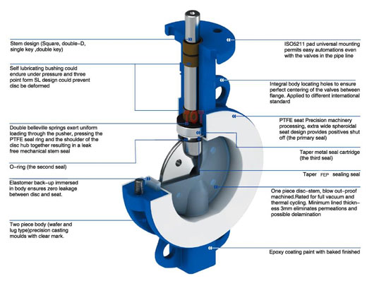
Stem Design: Square, Double-0, Single key, Double key
Valve Stem: Equipped with self-lubricating shaft bearing, which can reduce the torque and maintenance without oil filling (in contrast, smaller actuators can be selected to reduce the cost
Gasket: The fourth stage is loaded with elastic gasket, which continuously gives the valve seat pressure to produce the first main seal. After testing, the effect is very stable
V-ring: The second seal, up and down v-rings, cross each other and maintain continuously
Elastic Spacer: Elastomer back-up immersed in body ensures zero leakage between disc and seat.
Body: Two piece body (wafer and lug type)precision casting moulds with clear mark
- IS05211 pad universal mounting permits easy automations even with the valves in the pipe line
- Integral body locating holes to ensure perfect centering of the valves between flange. Applied to different international standard
- Outdoor epoxy baking paint, excellent corrosion resistance
Seat: Increase the thickness of the inner wall of the valve seat (more than 6mm) to resist the pipeline flushing. The FEP high-temperature expansion valve body is specially processed with reverse buckle groove to prevent the risk of leakage after flange face clamp compression
Dic: Integrated disc, blow out proof design. There are through holes on the valve disc, which can effectively strengthen the adhesion of lining materials, and is suitable for vacuum and thermal cycle
FEP Lined Butterfly Valve Materials
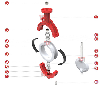
| NO. | Description | Materials | Materials According to Norms | |||
| ASTM | JIS | DIN | ||||
| 1 | BODY | Carbon Steel, Stainless Steel, Ductile lron | A216-WCB, A351-CF8, ASTM A395 | G5151 SCPH2, G5121 SCS13A, FCD400 | GS-45(1 .0446), G-X6CrNiMo1810, GGG-40 (0.7040) | |
| 2 | DISC | Carbon Steel, Stainless Steel | PTFE, FEP, PFA | A216-WCB, A351-CF8 | G5151 SCPH2, G5121 SCS13A | GS–45(1.0446), G-X6CrNiMo1810 |
| 3 | SEAT | PTFE/FEP/PFA | — | — | — | |
| 4 | ELASTIC SPACER | EPDM | — | — | — | |
| 5 | AXLE SLEEVE | Stainless Steel + PTFE | — | — | — | |
| 6 | Gland | Stainless Steel | 304 | SUS304 | 1.4301 | |
| 7 | STEM | Stainless Steel | 410, 304 | SUS410, SUS304 | 1.4006, 1.4301 | |
| 8 | BELLEVILLE SPRING | Stainless Steel | 304 | SUS304 | 1.4301 | |
| 9 | V-RING | PTFE | — | — | — | |
| 10 | HEX BOLT | Stainless Steel | 304 | SUS304 | 1.4301 | |
Wafer & Lug Type FEP Lined Butterfly Valve Dimension
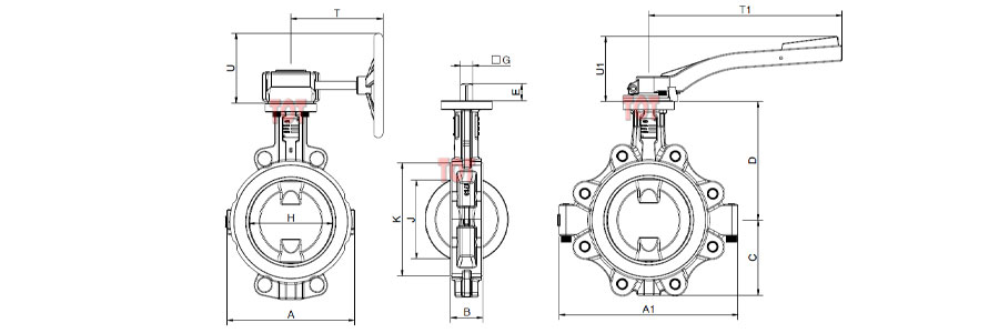
| DN | NPS | Dimensions in mm | ISO 5211 | Weight | Cv | Torque | ||||||||||||||||
| Wafer | Lug | Handle | Gearbox | |||||||||||||||||||
| mm | in | A | A1 | B | C | D | E | G | H | J | K | T | T1 | U | U1 | [Kg] | [Kg] | [Kg] | [Kg] | [N∙m] | ||
| 40 | 1½ | 91 | 146 | 33 | 55 | 109 | 13 | 11 | 40.5 | 23.5 | 78 | 160 | 200 | 95 | 76 | F05 | 2.5 | 3.2 | 0.45 | 1.6 | 190 | 35 |
| 50 | 2 | 102 | 159 | 43 | 65 | 134.5 | 13 | 11 | 50.5 | 26.5 | 89.5 | 160 | 200 | 95 | 76 | F05 | 3 | 4.7 | 0.45 | 1.6 | 210 | 40 |
| 65 | 2½ | 118 | 204 | 46 | 74 | 149 | 13 | 11 | 65.5 | 46.5 | 104.5 | 160 | 200 | 95 | 76 | F05 | 3.4 | 5.8 | 0.45 | 1.6 | 300 | 48 |
| 80 | 3 | 135 | 226 | 46 | 84 | 156 | 13 | 11 | 79.5 | 65 | 121.5 | 160 | 200 | 95 | 76 | F05 | 4 | 6.5 | 0.45 | 1.6 | 410 | 56 |
| 100 | 4 | 158 | 260 | 52 | 100 | 179 | 16 | 14 | 98.5 | 84 | 144 | 160 | 260 | 127 | 85 | F07 | 5.8 | 8.5 | 0.65 | 1.8 | 710 | 82 |
| 125 | 5 | 184 | 289 | 56 | 116 | 194 | 19 | 17 | 120.5 | 107 | 168.5 | 160 | 350 | 127 | 102 | F07 | 7.6 | 10.6 | 0.8 | 1.8 | 1150 | 120 |
| 150 | 6 | 214 | 315 | 56 | 132 | 209 | 19 | 17 | 146.5 | 136 | 196.5 | 160 | 350 | 127 | 102 | F07 | 10 | 13.9 | 0.8 | 1.8 | 1750 | 170 |
| 200 | 8 | 270 | 383 | 60 | 164 | 237.5 | 24 | 22 | 195.5 | 186 | 251.5 | 215 | – | 153 | – | F10 | 16.7 | 17.9 | – | 3 | 3550 | 298 |
| 250 | 10 | 330 | 456 | 68 | 195 | 275 | 24 | 22 | 245.5 | 236 | 305.5 | 225 | – | 185 | – | F10 | 24 | 27.2 | – | 5 | 5100 | 390 |
| 300 | 12 | 384 | 528 | 78 | 222 | 300 | 29 | 27 | 292.5 | 282 | 354.5 | 325 | – | 248 | – | F12 | 32 | 35.8 | – | 10 | 8870 | 590 |
| 350 | 14 | 448 | 570 | 78 | 258 | 325 | 29 | 27 | 343.5 | 334 | 408.5 | 325 | – | 248 | – | F12 | 57 | 87 | – | 10 | 9200 | 810 |
| 400 | 16 | 510 | 652 | 102 | 294 | 365 | 38 | 36 | 392 | 378.5 | 459 | 230 | – | 217 | – | F14 | 69 | 101 | – | 18.5 | 14500 | 1260 |
| 450 | 18 | 602 | 672 | 114 | 314 | 400 | 38 | 36 | 446 | 431 | 516 | 230 | – | 217 | – | F14 | 82 | 137 | – | 18.5 | 20100 | 1470 |
| 500 | 20 | 657 | 721 | 127 | 351 | 444 | 38 | 36 | 489 | 472 | 569 | 335 | – | 285 | – | F16 | 96 | 158 | – | 41 | 22000 | 1800 |
| 600 | 24 | 766 | 852 | 154 | 410 | 510 | 48 | 46 | 588 | 567 | 669 | 335 | – | 285 | – | F16 | 141 | 242 | – | 41 | 31000 | 2995 |
| 700 | 28 | 906 | 992 | 165 | 454 | 553 | 57 | 55 | 699.5 | 679 | 780 | 385 | – | 310 | – | F25 | 182 | 290 | – | 52 | 39500 | 3400 |
*The weight of the wafer and lug type is bare shaft
Flanged Type FEP Lined Butterfly Valve Dimension
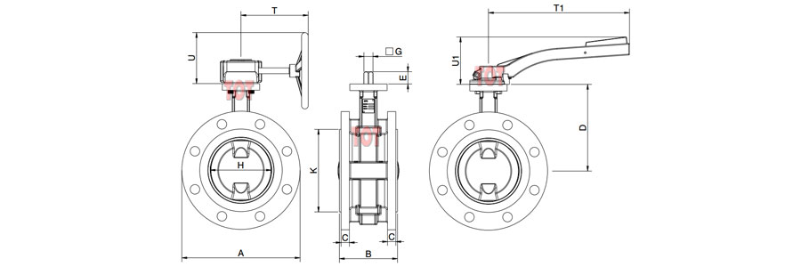
| DN | NPS | Dimensions in mm | ISO 5211 | Weight | Cv | Torque | ||||||||||||||||
| PN10 | PN16 | Double Flanged | Handle | Gearbox | ||||||||||||||||||
| mm | in | A | C | A | C | B | D | E | ☐G | H | K | T | T1 | U | U1 | [Kg] | [Kg] | [Kg] | [N∙m] | |||
| 40 | 1½ | 150 | 16 | 150 | 16 | 106 | 109 | 13 | 11 | 40.5 | 78 | 160 | 200 | 95 | 76 | F05 | 10.7 | 0.45 | 1.6 | 190 | 35 | |
| 50 | 2 | 165 | 16 | 165 | 16 | 108 | 134.5 | 13 | 11 | 50.5 | 89.5 | 160 | 200 | 95 | 76 | F05 | 16 | 0.45 | 1.6 | 210 | 40 | |
| 65 | 2½ | 185 | 16 | 185 | 16 | 112 | 149 | 13 | 11 | 65.5 | 104.5 | 160 | 200 | 95 | 76 | F05 | 19.1 | 0.45 | 1.6 | 300 | 48 | |
| 80 | 3 | 200 | 18 | 200 | 18 | 114 | 156 | 13 | 11 | 79.5 | 121.5 | 160 | 200 | 95 | 76 | F05 | 24 | 0.45 | 1.6 | 410 | 56 | |
| 100 | 4 | 220 | 18 | 220 | 18 | 127 | 179 | 16 | 14 | 98.5 | 144 | 160 | 260 | 127 | 85 | F07 | 30 | 0.65 | 1.8 | 710 | 82 | |
| 125 | 5 | 250 | 20 | 250 | 20 | 140 | 194 | 19 | 17 | 120.5 | 168.5 | 160 | 350 | 127 | 102 | F07 | 35.3 | 0.8 | 1.8 | 1150 | 120 | |
| 150 | 6 | 285 | 20 | 285 | 20 | 140 | 209 | 19 | 17 | 146.5 | 196.5 | 160 | 350 | 127 | 102 | F07 | 51.8 | 0.8 | 1.8 | 1750 | 170 | |
| 200 | 8 | 340 | 22 | 340 | 22 | 152 | 237.5 | 24 | 22 | 195.5 | 251.5 | 215 | – | 153 | – | F10 | 65.5 | – | 3 | 3550 | 298 | |
| 250 | 10 | 395 | 24 | 405 | 24 | 165 | 275 | 24 | 22 | 245.5 | 305.5 | 225 | – | 185 | – | F10 | 88.7 | – | 5 | 5100 | 390 | |
| 300 | 12 | 445 | 23 | 460 | 25 | 178 | 300 | 29 | 27 | 292.5 | 354.5 | 325 | – | 248 | – | F12 | 107.9 | – | 10 | 8870 | 590 | |
| 350 | 14 | 505 | 23 | 520 | 27 | 190 | 325 | 29 | 27 | 343.5 | 408.5 | 325 | – | 248 | – | F12 | 166.4 | – | 10 | 9200 | 810 | |
| 400 | 16 | 565 | 23 | 580 | 29 | 216 | 365 | 38 | 36 | 392 | 459 | 230 | – | 217 | – | F14 | 200.5 | – | 18.5 | 14500 | 1260 | |
| 450 | 18 | 615 | 25 | 640 | 37 | 222 | 400 | 38 | 36 | 446 | 516 | 230 | – | 217 | – | F14 | 289.7 | – | 18.5 | 20100 | 1470 | |
| 500 | 20 | 670 | 24 | 715 | 40 | 229 | 444 | 38 | 36 | 489 | 569 | 335 | – | 285 | – | F16 | 366 | – | 41 | 22000 | 1800 | |
| 600 | 24 | 780 | 30 | 840 | 50 | 267 | 510 | 48 | 46 | 588 | 669 | 335 | – | 285 | – | F16 | 466 | – | 41 | 31000 | 2995 | |
* The weight of the double flanged type is bare shaft
* We are not just providing simple quotes but experts in selection, calculation, and drawing.
