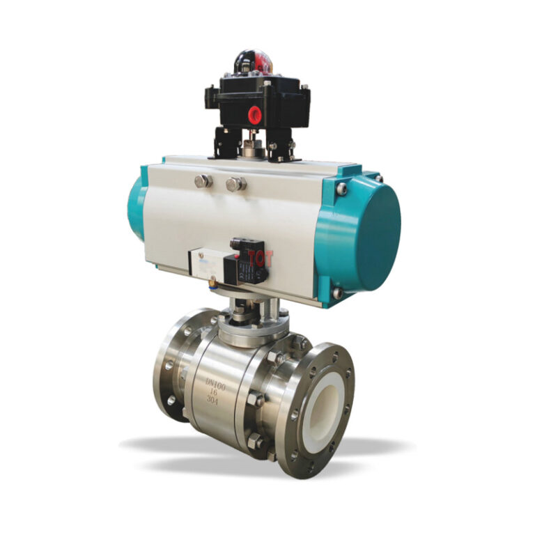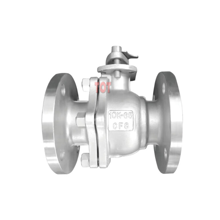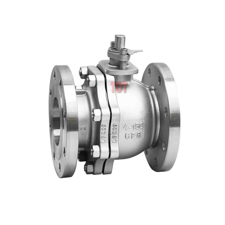
Ceramic Hemispherical Valve
Ceramic hemispherical valve is a valve type with a structure between ball valve and gate valve, which uses a hemispherical closing piece with ceramic lining. The ceramic hemispherical valves we provide are designed and manufactured in accordance with API 6D standards in terms of size, tolerance, pressure level, test requirements, sealing performance, etc.
If you’re looking for a valve that can handle abrasive slurries, solid-laden fluids, or high-flow systems without clogging or frequent maintenance, our API 6D standard ceramic hemispherical valve is your ideal solution.
Description
Ceramic hemispherical valve combines ceramic lining and is a high-performance valve with high wear and corrosion designed and manufactured for your conveying system containing granular media such as powder, slurry, coal powder, dry ash, limestone slurry, catalyst, etc.
The ceramic hemispherical valve provided by TOT is designed for reliability and is widely used in desulfurization systems in power plants, mineral processing pipelines, and general fluid control pipelines in the chemical industry. If you are not using it in an extremely corrosive environment, its durability and sealing performance are something you don’t need to consider too much.
As a professional valve manufacturer with years of export experience, we deliver not only a product—but a long-term solution tailored for industrial challenges. Whether you’re replacing metal-seated valves that wear out too quickly or looking for a more stable long-life valve, our ceramic hemispherical valve will exceed expectations.
Executive Standards
Note: After passing the valve experiment, it is necessary to eliminate accumulated water in the cavity, dry the inner cavity with air, apply anti-rust oil, and block both ends of the diameter with caps.
| Design & Manufacturing | Flange Connection | Inspection & Testing | Structure Length |
| API 6D | GB/T9113 | GB/T13927 | Manufacturers standards or customer requirements |
Designed for Demanding Applications
What sets this valve apart isn’t just the ceramic lining—it’s the engineering behind every detail:
– High-Hardness Zirconia Ceramic Trim: The sealing surface and flow path are protected with precisely machined zirconia (ZrO₂) ceramic components, offering exceptional wear resistance, oxidation resistance, and extended service life.
– API 6D-Compliant Design & Testing: Fully designed and tested in accordance with API 6D, ensuring international standards for dimension, pressure performance, sealing integrity, and material selection.
– Full-Bore, Non-Clogging Eccentric Design: The hemispherical shut-off element rotates on an eccentric axis, minimizing friction during operation. This design allows for full-bore flow and eliminates jamming caused by sediment or solids—ideal for slurry and particulate-heavy media.
– Reinforced Valve Body: The valve housing is cast with wall thickness exceeding standard requirements, enhancing structural reliability and longevity even under cyclic loading conditions.
– Precision-Ground Sealing Surface: The ceramic-to-ceramic sealing interface is meticulously polished for tight shut-off, minimizing leakage and wear over long-term use.
Main Component Materials
| Number | Name | Material | Number | Name | Material |
|---|---|---|---|---|---|
| 1 | Valve Body | WCB | 9 | Screw | B7 |
| 2 | Spool | WCB Spray Tungsten Carbide | 10 | Valve Stem | 17-4PH |
| 3 | Lower Valve Stem | 2Cr13 | 11 | Upper Bushing | PTFE |
| 4 | O-ring Seal | Nitrile Rubber | 12 | Stuffing Box | 20 |
| 5 | Bottom | 20 | 13 | Filler | Flexible Graphite |
| 6 | Valve Seat | Engineering Ceramics | 14 | Packing Gland | 20 |
| 7 | Spherical Sealing Ring | Engineering Ceramics | 15 | Support | WCB |
| 8 | Pressing Ring | A105 | 16 | Manual Worm Gear Device | |
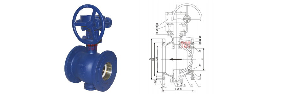
Main Appearance and Connection Dimensions (Unit: mm)
| Size | L | d | D | D1 | D2 | F | C | n-Φd | |
|---|---|---|---|---|---|---|---|---|---|
| DN | In | ||||||||
| 50 | 2″ | 178 | 40 | 165 | 125 | 99 | 2 | 20 | 4-18 |
| 65 | 2-1/2″ | 190 | 50 | 185 | 145 | 118 | 2 | 20 | 4-18 |
| 80 | 3″ | 203 | 65 | 200 | 160 | 132 | 2 | 20 | 8-18 |
| 100 | 4″ | 229 | 80 | 220 | 185 | 156 | 2 | 22 | 8-18 |
| 125 | 5″ | 245 | 100 | 250 | 210 | 184 | 2 | 22 | 8-18 |
| 150 | 6″ | 267 | 125 | 285 | 240 | 211 | 2 | 24 | 8-22 |
| 200 | 8″ | 292 | 150 | 340 | 295 | 266 | 2 | 24 | 8-22 |
| 250 | 10″ | 330 | 200 | 395 | 350 | 319 | 2 | 26 | 12-22 |
| 300 | 12″ | 356 | 250 | 445 | 400 | 370 | 2 | 26 | 12-22 |
| 350 | 14″ | 430 | 300 | 505 | 460 | 429 | 2 | 26 | 16-22 |
| 400 | 16″ | 530 | 350 | 565 | 515 | 480 | 2 | 26 | 16-26 |
* We are not just providing simple quotes but experts in selection, calculation, and drawing.
