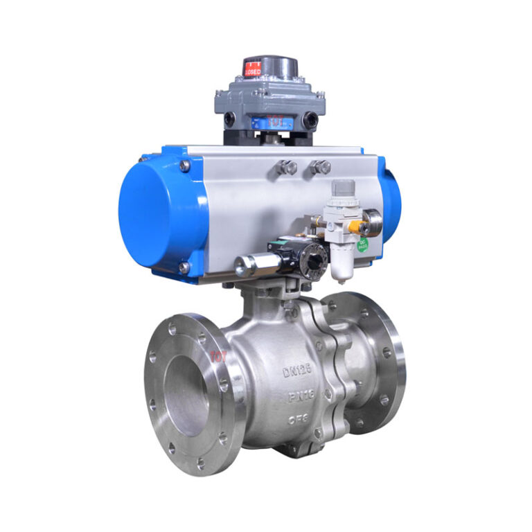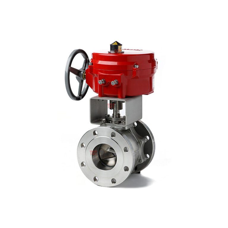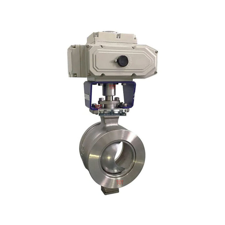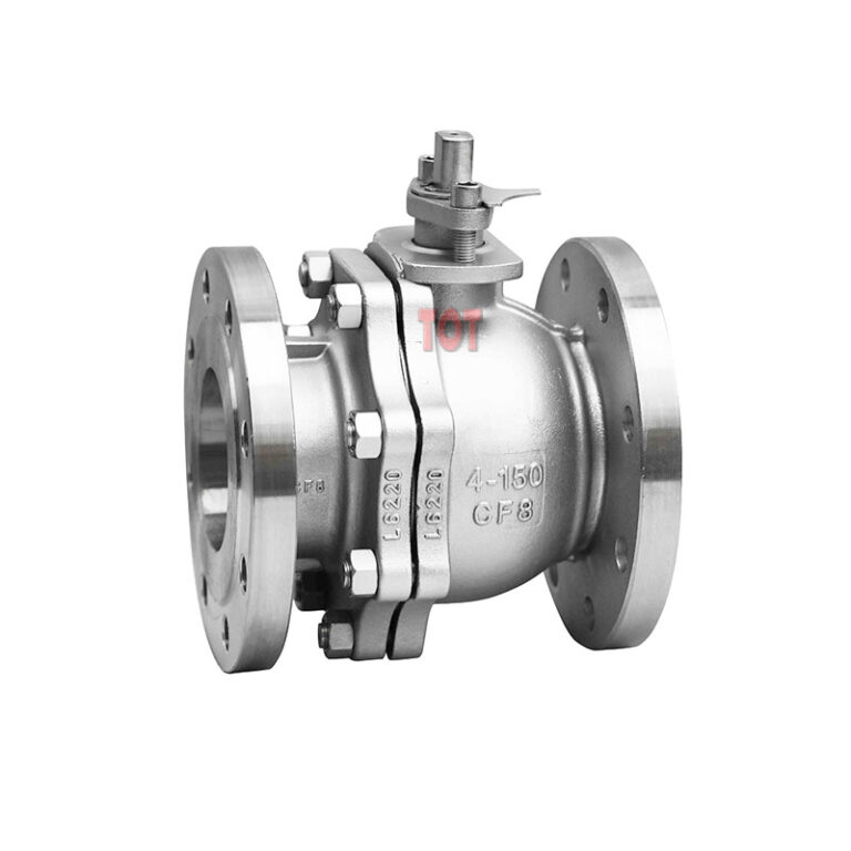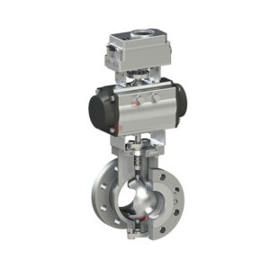
Flange Segmented Ball Valve
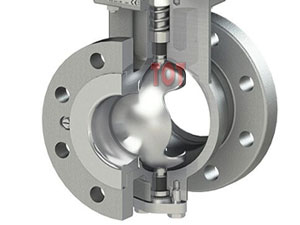
Flange segmented ball valves, also known as flange V-notch ball valves, are quarter-turn valves used to control pipeline fluid flow. The ball of this type of ball valve has a V-notch, which has a sharp edge. During the rotation of the ball, there is a wiping effect between the closing parts, which has a strong cutting force on the medium. The V-notch of the ball forms a fan-shaped area with the valve seat flow channel, which can change the flow channel cross-sectional area during the rotation process, which can achieve appropriate flow regulation and has high capacity.
TOT Valve As a reliable segmented ball valve manufacturer, it builds valves for harsh applications. Its rugged design can cope with harsh processes and fluid challenges containing solid particles, fibrous/unclean media. TOT provides precise and reliable control and extremely high rangeability, making it an ideal choice for chemical processing and oil and gas applications.
Contact us now to choose a solution that can improve the performance efficiency and stability of your fluid control system.
Description
Segmented ball valves can easily control corrosive fluid slurries and work in environments that require high durability.
TOT segmented ball valves are called “segmented” because the ball inside the valve is not a complete sphere, but a V-notch on the sphere. This valve design can give your fluid control system high capacity, tight sealing and non-clogging flow control.
Segmented ball valves are an angular turn regulating valve with the same sealing performance as ordinary ball valves, and both regulating and switching functions. At TOT Valve, you can choose to match it with pneumatic or electric actuators and use it in your industrial process automation system.
We also provide customized segmented ball valves according to your required size, material, end connection method and surface treatment. If you are not sure about your specific needs, the TOT Valve team will consider the pressure level, operating temperature, operation type and other factors of your application scenario to make a suitable recommendation for you. Contact us now and let TOT Valve help your business take off.
Flange Segmented Ball Valve Features
- Quarter-turn valve
- V-notch provides equal percentage flow control
- Uni-body prevents external leakage
- Durable metal seat
- Live loaded packing, protected bearing
- ISO 5211 Direct-Mounting for easy automation
- Extremely low actuator torque
- Stainless steel, carbon steel, alloy materials available
- Pressure Level: PN10-25; 150Lb; 10K
- Drive Device: manual, pneumatic, electric, electro-hydraulic
- Accessories: electrical valve positioner, solenoid valve, limit switch, air filter pressure reducer, etc.
Design Standards
TOT Valve provides different types of segmented ball valves that comply with ISO and ASME standards.
| Pressure & Temperature | Structural Length | Temperature Range | Sealing & Strength Test Standards |
|---|---|---|---|
| ASME B16.34-2003, ISO 7005-1 | ISA S75.04-1995, IEC/DIN 534-3-2 | -29℃ ~ 450℃ | GB/T 4213-2007 |
Flange Segment Ball Valve Main Components and Materials
The TOT segmented ball valve is well-made and easy to operate and clean. It consists of a durable stainless steel metal body, self-lubricating bearings, a low-friction shaft and a segmented ball. In addition, a variety of seat options are available, such as metal seats or soft seats. Below is a summary of the main components of the segmented ball valve and their component materials for you to choose from.
Valve Stem: The valve stem is finely ground and matched with the actuator with high precision, making the valve backlash small
Valve Body: The valve body adopts an integral structure with good rigidity, reducing the possibility of leakage
Packing: The packing is made of high-quality PTFE material with good sealing
Bearing: The bearing adopts self-lubricating bearing with high load-bearing capacity, small friction coefficient, and reduced operating torque
Spring: The spring adopts a special hexagonal spring, which reduces the friction between the ball and the valve seat while providing preload, making the valve operating torque smaller
Ball: The ball with a V-notch is hard chrome plated, ion nitrided or supersonic sprayed on the spherical surface to improve the surface hardness, so that the ball mouth has a hard and sharp edge with shearing function for the medium
Valve Seat: The special bonnetless design makes there is no dead angle between the valve seat and the valve body, the medium is not easy to accumulate, and the solid particle medium will not be stuck
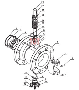
| No. | Name | Material | ||
|---|---|---|---|---|
| 1 | Body | WCB | CF8 | CF8M |
| 2 | Core | CF8 surface hard nickel plating | CF8 surface hard nickel plating | CF8M surface hard nickel plating |
| 3 | Cylindrical Pin | 304 | 304 | 316 |
| 4 | Seat | 304 cladding carbide | 304 cladding carbide | 316 cladding carbide |
| 5 | Spring | 316 | 316 | 316 |
| 6 | O-ring | Fluororubber | Fluororubber | Fluororubber |
| 7 | Self-lubricating bearing | 304+PTFE | 304+PTFE | 316+PTFE |
| 8 | Lower Valve Stem | 20Cr13 | 304 | 316 |
| 9 | O-ring | Fluororubber | Fluororubber | Fluororubber |
| 10 | Rear Gland | WCB | CF8 | CF8M |
| 11 | Ring Washer | PTFE | PTFE | PTFE |
| 12 | Adjusting Washer | PTFE | PTFE | PTFE |
| 13 | Flat Washer | Q235 | 304 | 304 |
| 14 | Bolt | 25 | 304 | 304 |
| 15 | Stud | 25 | 304 | 304 |
| 16 | Self-lubricating bearing | 304+PTFE | 304+PTFE | 316+PTFE |
| 17 | Flat key | 20Cr13 | 304 | 316 |
| 18 | Lower Packing | PTFE | PTFE | PTFE |
| 19 | Middle Packing | PTFE | PTFE | PTFE |
| 20 | Upper Packing | PTFE | PTFE | PTFE |
| 21 | Package Gland | WCB | CF8 | CF8M |
| 22 | Nut | 35 | 304 | 304 |
| 23 | Upper Valve Stem | 20Cr13 | 304 | 316 |
Flange Segment Ball Valve Overall Dimensions
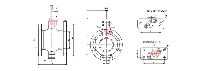
TOT Valves can provide you with various sizes of flange segmented ball valves. We have listed some flange segmented ball valve sizes suitable for PN16 and 150LB for your reference.
If you do not have the flange segmented ball valve size you need, you can contact us immediately. Our professional sales manager will contact you and can provide you with exclusive ODM and OEM services.
| PN16 | ||||||||||||||
|---|---|---|---|---|---|---|---|---|---|---|---|---|---|---|
| DN | A | B | b1 | f | C | T | Y | L | φd | h | S | K | M | Z |
| 25 | 102 | 115 | 16 | 2 | 38 | 81 | 73 | 75 | 16 | 35 | 75 | – | 2-M10 | 5 |
| 32 | 102 | 140 | 18 | 2 | 45 | 86 | 78 | 75 | 16 | 35 | 75 | – | 2-M10 | 5 |
| 40 | 114 | 150 | 18 | 2 | 50 | 90 | 80 | 75 | 16 | 35 | 75 | – | 2-M10 | 5 |
| 50 | 124 | 165 | 20 | 2 | 62 | 93 | 90 | 75 | 16 | 35 | 75 | – | 2-M10 | 5 |
| 65 | 145 | 185 | 20 | 2 | 73 | 108 | 105 | 75 | 16 | 35 | 75 | – | 2-M10 | 5 |
| 80 | 165 | 200 | 20 | 2 | 90 | 123 | 118 | 75 | 20 | 35 | 90 | 28 | 4-M10 | 6 |
| 100 | 194 | 220 | 22 | 2 | 115 | 138 | 130 | 75 | 20 | 35 | 90 | 28 | 4-M10 | 6 |
| 125 | 194 | 250 | 22 | 2 | 134 | 148 | 145 | 90 | 25 | 40 | 90 | 28 | 4-M10 | 8 |
| 150 | 229 | 285 | 24 | 2 | 164 | 170 | 170 | 94 | 30 | 40 | 110 | 40 | 4-M12 | 8 |
| 200 | 243 | 340 | 24 | 2 | 206 | 200 | 201 | 94 | 30 | 50 | 110 | 40 | 4-M12 | 8 |
| 250 | 297 | 405 | 26 | 2 | 260 | 240 | 237 | 98 | 40 | 60 | 135 | 40 | 4-M16 | 12 |
| 300 | 338 | 460 | 28 | 2 | 316 | 286 | 282 | 98 | 40 | 90 | 135 | 40 | 4-M16 | 12 |
| 350 | 400 | 520 | 30 | 2 | 372 | 330 | 337 | 125 | 50 | 60 | 140 | 64 | 4-M16 | 14 |
| 400 | 400 | 580 | 32 | 2 | 420 | 367 | 372 | 172 | 60 | 80 | 140 | 64 | 4-M20 | 18 |
| 450 | 520 | 640 | 40 | 2 | 470 | 422 | 432 | 172 | 70 | 90 | 190 | 90 | 4-M24 | 20 |
| 500 | 600 | 715 | 44 | 2 | 516 | 490 | 498 | 180 | 80 | 100 | 190 | 90 | 4-M24 | 22 |
| 150LB | ||||||||||||||
|---|---|---|---|---|---|---|---|---|---|---|---|---|---|---|
| Inch | A | B | b1 | f | C | T | Y | L | φd | h | S | K | M | Z |
| 1″ | 102 | 108 | 14.5 | 2 | 38 | 81 | 73 | 75 | 16 | 35 | 75 | – | 2–M10 | 5 |
| 1¼” | 102 | 115 | 14.5 | 2 | 45 | 86 | 78 | 75 | 16 | 35 | 75 | – | 2–M10 | 5 |
| 1½” | 114 | 127 | 14.5 | 2 | 50 | 90 | 80 | 75 | 16 | 35 | 75 | – | 2–M10 | 5 |
| 2″ | 124 | 152 | 16.3 | 2 | 62 | 93 | 90 | 75 | 16 | 35 | 75 | – | 2–M10 | 5 |
| 2½” | 145 | 180 | 18 | 2 | 76 | 108 | 95 | 75 | 20 | 35 | 90 | 28 | 4–M10 | 6 |
| 3″ | 165 | 191 | 19.5 | 2 | 90 | 123 | 118 | 75 | 20 | 35 | 90 | 28 | 4–M10 | 6 |
| 4″ | 194 | 230 | 24 | 2 | 115 | 138 | 130 | 90 | 25 | 35 | 90 | 28 | 4–M10 | 6 |
| 5″ | 194 | 255 | 24.3 | 2 | 134 | 148 | 145 | 80 | 25 | 35 | 90 | 28 | 4–M10 | 8 |
| 6″ | 229 | 280 | 26 | 2 | 164 | 170 | 170 | 90 | 30 | 50 | 110 | 40 | 4–M12 | 8 |
| 8″ | 243 | 340 | 29 | 2 | 200 | 200 | 201 | 94 | 30 | 50 | 110 | 40 | 4–M12 | 10 |
| 10″ | 297 | 405 | 30.6 | 2 | 260 | 240 | 237 | 98 | 40 | 60 | 135 | 40 | 4–M16 | 12 |
| 12″ | 338 | 485 | 32.2 | 2 | 316 | 286 | 282 | 100 | 50 | 60 | 135 | 40 | 4–M16 | 12 |
| 14″ | 400 | 535 | 35.4 | 2 | 372 | 330 | 337 | 125 | 50 | 60 | 140 | 64 | 4–M16 | 14 |
| 16″ | 437 | 580 | 37 | 2 | 420 | 367 | 372 | 172 | 60 | 70 | 160 | 72 | 4–M20 | 18 |
| 18″ | 520 | 635 | 40.1 | 2 | 470 | 422 | 432 | 170 | 70 | 100 | 190 | 90 | 4–M24 | 20 |
| 20″ | 600 | 700 | 44 | 2 | 516 | 490 | 498 | 180 | 80 | 100 | 190 | 90 | 4–M24 | 22 |
Fast Response & Competitive Pricing Start Here
* We are not just providing simple quotes but experts in selection, calculation, and drawing.
